


Die casting is a crucial process in modern manufacturing, and the design of die casting dies plays a vital role in ensuring the quality and efficiency of the final product. This comprehensive guide explores the key factors influencing die casting die design and casting mould design, offering insights into various aspects critical for achieving optimal results.
Factors in Die Casting Die Design:
Chosen Types of Aluminum Die Casting:
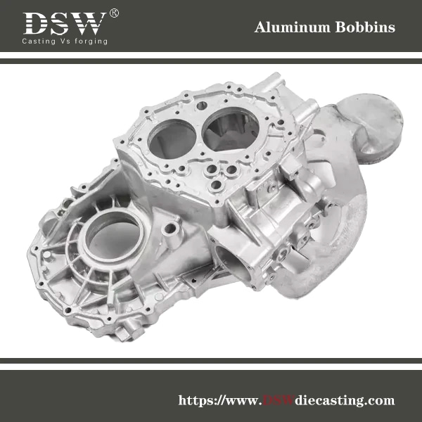
High-Pressure Die Casting (HPDC): This method involves injecting molten aluminium into a die under high pressure. HPDC produces intricate shapes with excellent surface finish and dimensional accuracy. Due to its efficiency and speed, it is ideal for high-volume production.
Gravity Die Casting (GDC): In this method, molten aluminum is poured into the die using gravity. GDC is favoured for producing parts with fewer porosity issues and allows for heat treatment. However, it is generally less efficient than HPDC regarding production speed.
Low-pressure die Casting (LPDC) involves pushing molten aluminum into the die cavity under low pressure, typically around 5-15 psi. This method is well-suited for producing high-integrity, complex parts with improved mechanical properties. LPDC minimizes porosity and enhances dimensional accuracy and surface finish. It is ideal for larger castings and offers versatility with various aluminum alloys.
General Wall Thickness Considerations: Wall thickness is a critical factor when designing casting mould dies. Uniform wall thickness ensures even cooling and reduces the risk of defects such as warping and shrinkage. To achieve optimal results, design considerations must account for material flow and cooling rates.

Aluminum Die Casting Tonnage Calculation:
Clamping Force Determination: The clamping force is essential to keep the die closed during the injection process. It prevents flash defects and ensures the quality of the casting.
Calculation Formula Explained: The clamping force can be calculated using the formula: Clamping Force(T)=Projected Area(A)×Injection Pressure(P)\text{Clamping Force} (T) = \text{Projected Area} (A) \times \text{Injection Pressure} (P)Clamping Force(T)=Projected Area(A)×Injection Pressure(P) where AAA is the projected area of the casting and PPP is the injection pressure.
Aluminum Die Casting Shrinkage:
Impact of Shrinkage on Metal Materials: Shrinkage occurs as the molten metal cools and solidifies, reducing its volume. This can lead to defects such as internal voids and surface sink marks.
Factors Affecting Shrinkage: Key factors include product structure, wall thickness, part size, and cooling rate. Proper analysis and design adjustments are necessary to mitigate shrinkage effects.
Die Casting Gate Area Calculation: The gate area is crucial for controlling the flow of molten metal into the die cavity. Proper calculation of the gate size ensures efficient mold filling and minimizes defects. Factors to consider include the flow rate, part geometry, and cooling requirements.
Design Tips for Die Casting
Designing die-cast components involves several critical variables influencing part quality, strength, and cost-efficiency. Below are enhanced tips covering casting die design, die casting mold design, and die casting tool design to guide the process.
1. Fillets, Radii, and Draft Angles
Incorporating appropriate fillets and radii helps prevent stress concentrations and improves the part’s structural integrity. Avoid sharp corners, use larger radii in high-stress areas, and maintain consistency in fillet sizes. Proper draft angles (typically 1-3 degrees) allow for easy ejection from the mold without damaging the part.
Improper fillets and radii can weaken components by altering their cross-sectional area. To ensure optimal strength, consider these design tips:
- Avoid sharp corners to prevent stress concentrations.
- Use larger radii in high-stress areas for added strength.
- Ensure appropriate radii at surface junctions to enhance joint strength.
- Maintain consistent fillets and radii throughout to preserve both strength and smoothness.
- Apply draft angles (typically 1-3°) to surfaces aligned with the mold opening direction for easy removal without surface damage, increasing for more complex shapes.
Pro Tip: For more complex geometries, consider increasing the draft angle to reduce the risk of defects and mold wear, which can extend die life.
2. Wall Thickness and Material Selection
The ideal wall thickness depends on the material and the part’s functional requirements. Thinner walls allow faster cooling but weaken the part if not adequately reinforced.
- Aluminium: 1.016 – 2.032 mm
- Zinc: 0.381 – 0.889 mm
- Magnesium: 1.016 – 2.54 mm
Material Choice Impact:
- Aluminum offers lightweight and excellent thermal conductivity, making it ideal for electronics and automotive components.
- Zinc is best for complex, detailed parts with high precision requirements.
- Magnesium is lightweight and used where weight reduction is critical (e.g., aerospace).
3. Ribs and External Corners
Adding ribs reinforces thin walls and enhances stiffness without drastically increasing weight. External corners should be rounded to minimize stress concentrations and improve the part’s durability. Uniform rib placement ensures even load distribution, reducing the risk of warping or failure.
Design Tip: Avoid excessive ribbing in non-load-bearing areas, as this can increase material usage and production costs.
4. Windows, Holes, and Complex Features
When designing windows and holes, consider their impact on the part’s strength. Avoid sharp edges and use larger draft angles, especially when the holes are positioned on the sides of the mold.
Cost-Saving Tip: Whenever possible, design holes and windows to be cast directly rather than post-machined to reduce lead time and cost. However, some features may require post-machining, particularly in high-precision applications.
5. Post-Machining Features
Post-machining adds precision but increases production time and cost. Features like undercuts, threads, or detailed geometries should be minimized during die cast mold design. Use cores wherever possible to reduce the need for post-processing.
Best Practice: Plan for easy access to these features during machining to reduce tool wear and time.
6. Parting Lines and Flash
Parting lines, where mold halves meet, should be strategically placed in less visible areas. Managing parting line thickness is crucial—thin lines may cause part failure upon ejection, while thick lines lead to uneven surfaces.
Flash Management: Flash often occurs along parting lines, so ensure your design allows easy removal during post-processing.
7. Surface Finish and Grades
Surface finishing greatly influences the part’s aesthetics and function. The choice of surface grade will depend on the end-use application, ranging from Grade-1 (Utility) to Grade-5 (Superior).
Industry Insight: Grade-5 finishes are typically used for consumer products with critical appearance, while Grade-1 is sufficient for internal components or industrial parts.
8. Thermal Management in Design
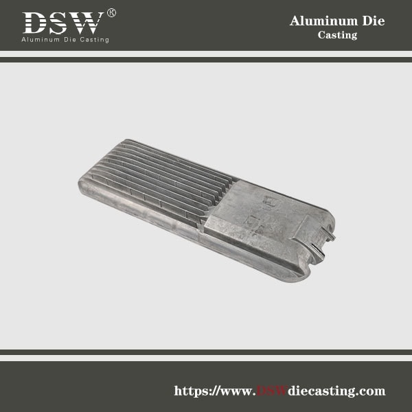
Heat dissipation is critical for applications like automotive or electronics. Optimizing the design with ribs and fins improves thermal management. Aluminum is preferred due to its high thermal conductivity, making it ideal for parts like heat sinks and enclosures.
9. Sustainability in Die Casting Design
Consider the environmental impact by designing with recyclable materials and minimizing material waste. Using simulation tools such as CFD (Computational Fluid Dynamics) or FEA (Finite Element Analysis) can help optimize the design for efficiency before production, saving both resources and costs.
Key Differences in Mold/Die Design
The fundamental distinction between injection molds and die casting dies lies in the materials used. Injection molding typically employs plastics, while die casting utilizes metal alloys. As a result, die casting molds are subjected to significantly higher pressures and temperatures, necessitating a reinforced mold structure. The feeding method, runner system, and cooling designs also differ. Both die-casting dies and injection molds commonly use tool steels, which are referred to as hot-work tool steels.
| Aspect | Plastic Injection Molds | Die Casting Molds |
| Structural Design | Typically incorporate a cooling system utilizing circulating water to regulate the mold temperature for uniform cooling. | In addition to a cooling system, equipped with a specialized venting system such as over flow well and air vent to expel air trapped during molten metal injection. |
| Runners & Gates | Design is more intricate, with components like gates, runners, and other structural elements. | Gates and runners are larger to accommodate high-velocity molten metal flow. |
| Gate dimensions are typically small, with various runner types (e.g., pin-point gates, side gates). | Ejection system requires enhanced strength and reliability due to higher ejection forces for die casting components. | |
| Ejection System | Ejection mechanisms include push rod and push plate ejection systems. | |
| Parting Line | Strategically placed to avoid flash and distortion | Designed for visual and functional consistency |
| Product Characteristics | Low density, typically ranging from 0.9 to 2.2 g/cm³. | Higher density, e.g., aluminum alloy die casting products have a density of approximately 2.7 g/cm³. |
| Capable of producing colorful, complex-shaped, thin-walled products (e.g., transparent plastic containers). | Offers superior strength and dimensional precision, ideal for parts requiring significant thickness and structural integrity. | |
| Generally lower dimensional accuracy with higher shrinkage rates, which vary based on material type. | Shrinkage rate is lower compared to plastic products. |
Casting flow Simulation Software
MAGMA Software for Casting Flow Analysis: Simulation tools in die design like MAGMA provide valuable insights into the die-casting process. They help analyze mold flow, cooling system efficiency, gate and runner design, tonnage requirements, and production parameters such as time and pressure.
Analysis of Cooling System, Gate and Runner Area, Tonnage, Time, and Pressure: By using simulation software, designers can optimize these factors to predict defects and enhance mold designs, improving the efficiency of the casting process.
Comprehensive Process Simulation
MAGMASOFT provides a fully integrated casting process simulation, covering every stage from mold filling and solidification to cooling and residual stress analysis. This comprehensive approach lets manufacturers gain in-depth insights into casting behavior, enhancing process control and efficiency.
Advanced Defect Prediction
The software accurately simulates casting conditions, enabling precise identification of potential casting defects, including porosity, shrinkage, hot tears, and cracks. By detecting these issues early in the design phase, manufacturers can implement proactive corrective measures to enhance casting integrity and reduce rework.
Optimized Mold Design
By simulating metal flow dynamics and solidification behavior, MAGMASOFT aids in optimizing mold designs to ensure uniform filling, minimize turbulence, and reduce thermal stress. This results in superior casting quality, lower defect rates, and improved material utilization.
Process Parameter Optimization
MAGMASOFT allows fine-tuning critical process parameters such as pouring temperature, mold temperature, cooling rates, and gating system design. This data-driven optimization helps achieve consistent, high-quality casting results while minimizing cycle times and production costs.
Modular and Scalable Design
The software features a modular architecture, enabling users to customize their simulation capabilities based on specific requirements. Modules such as MAGMAstress for residual stress analysis and MAGMAsemisolid for semi-solid casting processes provide specialized tools to address diverse casting challenges.
Autonomous Engineering
MAGMASOFT supports autonomous engineering, integrating automated simulation setup, virtual design of experiments (DoE), and advanced optimization algorithms. These capabilities significantly reduce engineering time, enhance process repeatability, and lower production costs by streamlining decision-making and accelerating design iterations.
Material in Casting Mold Design
Die Core Material Options:
- H13 Steel: Highly valued for its thermal conductivity and resistance to thermal fatigue, making it perfect for high-temperature die cores.
- SKD61 Steel offers excellent toughness and high-temperature performance. It suits aluminium, zinc, and copper alloy moulds, ejector pins, and barrels.
- 8418 Steel: Renowned for its resistance to thermal fatigue, shock, wear, and deformation. Ideal for molds used with zinc, magnesium, aluminium, and titanium alloys.
Die Base Material Options: Materials such as QT600, S50C, and QT550 are often used for die bases due to their durability and ability to withstand high-pressure conditions.
Die Casting Tooling Life:
Factors Affecting Tooling Life: Tooling life depends on several factors, including die material, design complexity, production volume, and maintenance practices.
Typical Tooling Life for Domestic and Export Scenarios: Tooling life can vary significantly based on production demands. Domestic tooling often has a shorter lifespan due to higher production volumes, while export tooling may have an extended life due to lower production rates.
Mastering the fundamentals of die casting die design is essential for achieving high-quality, cost-effective production. By considering factors such as casting method, tonnage calculation, shrinkage analysis, and simulation software utilization, designers can create dies that meet the demands of modern manufacturing. With meticulous attention to detail and a comprehensive understanding of the die casting process, designers can unlock the full potential of die casting as a manufacturing solution.


No comment