Die Casting Mold Components
Die-casting dies function as permanent molds and are typically composed of two parts arranged to open and close with vertical parting. When mounted on a die casting machine, one of the die halves remains stationary, referred to as the cover die or core side, while the other half moves for opening and closing. This movable half is known as the ejector die or cavity side.
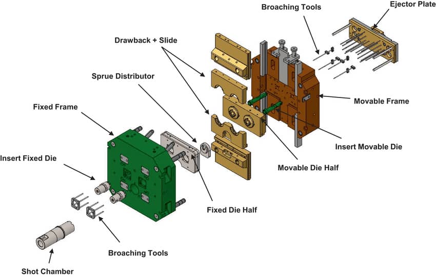
4 Main Parts of A Die
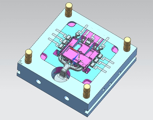
Cavity Plate/ Fixed Plate / A Plate:
The plate holding the cavity is often part of the mold and fixed to the machine. This fixed die half typically contains the runner, gate system, and cooling channels. It remains stationary during the injection casting process, also called a stationary die.
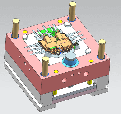
Core Plate/ Moveable Plate/ B Plate:
This is where the core is installed and typically forms the opposite side of the mold from the cavity plate. This Moving Half, also called the ejector side, contains the ejector pins that push out the casting after solidification.
Moving or Moveable Plate: This component typically moves along with the ejector plate. It can also help lock or open the mold.
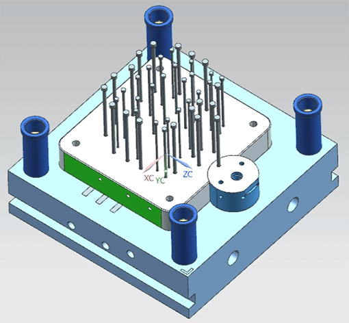
Ejector Plate:
The ejector plate pushes the casting out of the die after cooling and solidifying it, while the pins help ensure smooth and proper ejection.
The ejector system consists of the ejector plate, pins, and return pins.
Die casting dies are made from special die steels such as H13 and Anviloy 1150, designed to withstand high temperatures, mechanical wear, and heat checking. These materials ensure the die’s durability and dimensional stability, crucial for producing high-quality castings. Additionally, die cavities are machined to extremely close tolerances to ensure precision in the final cast part.
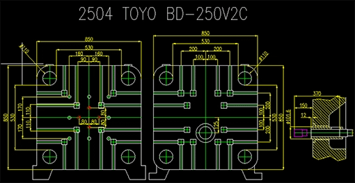
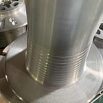
The shot sleeve is the component in a die-casting machine that holds and injects molten metal into the mold cavity under pressure. It is typically lengthy and designed to accommodate the entire shot of molten metal for one cycle.
Conversely, a short chamber describes a smaller or shorter variation of the shot sleeve. It could be utilized for particular purposes or in some machine designs where a smaller chamber is adequate to pour the molten metal into the mold. The chamber’s capacity and length define the main variations.
Construction of Stationary and Movable Die
The die casting die consists of two primary components: the fixed die and the movable die. The fixed die is securely connected to the machine’s injection unit and fastened to the machine’s head plate. In contrast, the movable die is installed on the die casting machine’s main plate. The movable half is responsible for opening and closing, allowing the molten metal to flow into the cavity and then enabling the casting to be ejected after cooling.
Fixed Mold: Core Component of the Die-Casting Mold
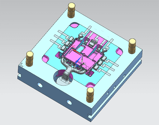
The fixed die is the primary cavity of the die mold. It is mounted on the die-casting machine’s mold mounting plate and connected to the nozzle or pressure chamber via a sprue.
The stationary die is mounted on the injection side of the die-casting machine and remains fixed during the casting process. It consists of the following components:
Structural Components
- Fixed Mold Insert – Forms part of the cavity and defines the external shape of the casting.
- Fixed Mold Sleeve Plate – Supports and secures the mold insert.
- Guide Pillar (Guide Pin) – Ensures precise alignment between the stationary and movable die when closing.
- Parting Line – The surface where the stationary and movable dies meet, ensuring proper sealing.
Metal Flow & Feeding System
- Sprue Sleeve – The entry point for molten metal from the injection unit.
- Sprue & Runner System – Channels that direct molten metal into the mold cavity.
- Gate – Controls the entry of molten metal into the cavity, influencing filling behavior.
Cooling & Venting System
- Cooling Channels – Integrated passages that regulate temperature, preventing overheating and thermal stress.
- Vents – Small openings that allow trapped air to escape, reducing porosity and defects.
Special Mechanisms
- Fixed Mold Core Pulling Mechanism – A system for forming undercuts or complex part features that require movement within the stationary die.
The fixed mold’s design effectively contains molten metal under pressure, providing the necessary cavity for the part to form. Its construction materials are specifically selected for durability, wear, heat, and mechanical stress resistance.
Movable Die (Moving Die) Components
Mechanism for Opening and Ejection
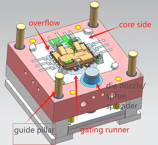
The movable die,also known as the back mold, is mounted on the ejector side of the die-casting machine. It moves forward to close the mold cavity and backward to eject the casting after solidification.
Structural Components
- Core – Forms the internal features of the casting, such as holes, recesses, and complex geometries.
- Guide Pins & Bushings – Work with the guide pillars on the stationary die to ensure precise alignment.
- Parting Surface – The contact surface between the stationary and movable die, ensuring proper sealing and minimizing metal leakage.
Ejection System
- Ejector Pins & Ejector Plate – Push the solidified casting out of the mold after cooling.
- Return Pins – Help reset the ejector plate to its original position after ejection.
Cooling & Venting System
- Cooling Channels – Maintain a controlled mold temperature, reducing defects and improving cycle times.
- Overflow & Venting System – Removes excess metal and trapped gases, reducing porosity in the casting.
Core Pulling & Sliding Components
- Wedge Block – Helps secure sliding parts and assists in locking mechanisms.
- Inclined Guide Pillar – A guiding component used for side core pulling or ejector movements, enabling the formation of complex features.
The design and function of the movable mold are crucial for ensuring precise part ejection, preventing deformation, and maintaining consistent part quality throughout the production cycle.
Core-Pulling Mechanism
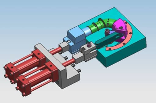
The core-pulling mechanism is crucial for producing die-casting components with intricate shapes or characteristics, such as deep grooves, undercuts, or internal cavities. The process seeks to safely and efficiently eradicate the voids generated by removable die cores inside the finished castings.
The system typically incorporates a variety of specialized components, including:
- Inclined Guide Posts: These are positioned at an angle to ensure smooth, consistent movement of the core-pulling action. The inclination helps minimize resistance during extraction, reducing the risk of damage to the part.
- Side Cores and Sliders: Side cores and slides create features the mold cavity cannot produce. Often installed on slides, side cores rotate laterally during the ejection operation to enable the removal of items having side apertures or undercuts.
- Guide Slides: These precision-machined components help guide the sliders’ movement or side cores, ensuring smooth, aligned motion and preventing wear or misalignment over time.
- Limit Blocks: To ensure precise mold closure, the slider must be held in a specific position, with the inclined guidepost adequately inserted. The total extraction distance, the core pulling distance sum, and an added safety margin are key parameters to consider.
- Screws, Springs, and Nuts: For the core-pulling system, mechanical components, including screws, springs, and nuts, create tension, adjustment, and locking mechanisms. While springs provide the required force for retraction of the cores, screws help in locking parts in place. Nuts fasten the system’s critical parts, ensuring operation stability.
The core-pulling mechanism is essential for molding processes that require high precision, especially in the automotive, aerospace, and medical device manufacturing industries, where intricate internal features are standard. This system allows manufacturers to produce parts with complex geometries while maintaining product integrity and quality control.
What Is Slide Die Casting?
A slide is a moveable die section used to cast undercuts or complicated exterior geometries. During the casting cycle, it allows portions of the mold to move to form the part’s outward characteristics. Hydraulic or mechanical systems usually control slides.
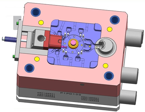
They operate by continuously entering and exiting the mold cavity to generate features such as channels or undercuts, which are unattainable with a traditional two-part mold.
What is the difference between core pulling and a slide in die casting?

Core pulling removes internal features (cores), whereas slide focusing on creating external features (undercuts and complex forms). Slides create intricate exterior shapes, while core pulling creates internal cavities or voids. Core pulling frequently involves removing the core from the mold chamber, while a slide is used to move the mold’s portion to facilitate the extraction of parts with intricate exterior designs.
What’s a mold base?
A mold base is the basic mold framework used in die casting, compression moulding, and injection molding. It provides a structure holding and supporting the other elements of the mold, including the core, cavity, ejector pins, and cooling channels. Stability and guaranteed correct alignment of the mold components during production come from the mold foundation.
Essential elements of a mold base
Die Block or Mold Plate: The main plates create the mold’s sides. Depending on the molding requirements, they can be changed or replaced; they house the mold cavity and core. While the cavity shapes the outside of the moulded object, the core is the section of the mold that creates its internal features.
Core and Cavity: The cavity creates the exterior form of the molded object; the core is the section of the mold that generates its internal features. Mounted within the mold base are the cavity and core.
Ejector Mechanism: Once the molded object has cooled and set, this system—which includes ejector pins or plates—helps push it out of the mold.
Cooling Channels: Designed within the mold base, cooling channels allow coolant to circulate through them to maintain a constant mold temperature, regulating the temperature during the molding process.
Guide Pins and Bushings: These guide pins and bushings guarantee accurate alignment of the mold halves when closed, enabling smooth operation.
The mold base offers the structural basis and necessary characteristics to allow the molding process, guaranteeing the mold runs effectively and generates high-quality parts.
2.Die Blocks: The Structural Groundwork
Die blocks house the cavity and core and offer the structural support for the whole mold, therefore resisting the great stresses of the casting process.
Usually coupled to the die-casting press of the machine, fixed die are the stationary half of the die mold. Usually supporting the major mold portions, it comprises the core. Larger, more complicated castings often use numerous cavities in the fixed die to generate several components simultaneously, hence improving manufacturing efficiency. In large-scale automobile part manufacture, for instance, a fixed die might contain a multi-cavity mold to generate many castings in one cycle.
The portion of the mold that opens and closes to let the casting be thrown off is the moving die—or ejector side. Usually using ejector pins to push the item out once it has cooled and formed, this die includes the cavity. For electronics sector precision die castings, the moving die could be fitted with sophisticated hydraulic or pneumatic systems to guarantee that it moves smoothly and effectively without distortion, which is absolutely vital for parts needing tight tolerances.
High-strength, wear-resistant steel alloys are used to create die blocks so they may withstand the constant strains and high temperatures the casting process exposes.
4. Sprue, Runner, and Gate: Guide Molten Metal Flow
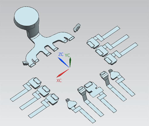
Ensuring effective injection of molten metal into the mold cavity without turbulence depends on the sprue, runner, and gate system, which also guarantees smooth flow and lowers flaws like cold shuts or voids.
The sprue is the point of entrance for molten metal entering the mold. Rising at the top of the mold, the sprue guarantees a regulated introduction of the metal. High-pressure die casting is usually used with a tapered form to hasten metal flow into the runner system. For significant parts like pump housings, the sprue design reduces air pockets and guarantees a constant metal flow.
Runner: This channel links the sprue to the gates, guiding the molten metal into the mold chamber. A well-made runner system guarantees a consistent fill by reducing the possibility of metal solidification before it enters the cavity. The runner system might have channels for complex castings, like those used in the car industry, so the molten metal can flow quickly into many cavities simultaneously, cutting down on cycle time.
The gate is the opening for molten metal used to reach the cavity. The gate’s size, form, and location determine how the metal fills the mold. A carefully placed gate ensures that the molten metal fills the mold evenly and without turbulence for a thin-walled item like a consumer electronics housing. Customizing gate design often requires matching the portion’s geometry to the metal’s flow characteristics.
5. Channels of cooling:
regulating the rate of solidification
Cooling is one of the most crucial elements of the die-casting process. It directly influences the solidification time and the quality of the final product. By absorbing heat from the molten metal integrated into the mold, cooling channels help control the cooling rate.
Channel design and mold material directly determine the efficiency of the cooling system. Developments in mold design, including conformal cooling channels that follow the form of the part, result in faster cooling rates and better casting quality. For example, conformal cooling systems are increasingly used in automobile die casting to produce parts with complicated geometries and strict tolerances since precise cooling channel design is crucial to prevent shrinkage, dimensional issues, or warping.
Ensuring airflow and avoiding defects in the vent system helps.
As molten metal is injected, proper ventilation is crucial for letting air and gases escape the mold. Inadequate venting can cause casting flaws such as air pockets, surface blebs, or insufficient fills.
Little channels or holes in the mold let gases and air escape during the injection. Proper ventilation ensures that the molten metal flows naturally into the hollow without getting caught by air. For medical devices with high-precision die casting, for instance, exact venting guarantees that gases do not cause porosity or weak areas in the finished item.
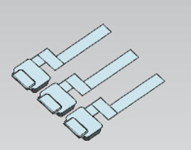
The vent system’s design must compromise economy and efficiency. Too much venting might cause the casting to lose molten or compromise its integrity. The best results are sometimes obtained by optimizing the vent placement using sophisticated simulation tools. Advanced venting systems are crucial in sectors like electronics, where components need great accuracy and limited tolerance for flaws to preserve product quality.






No comment