Mitigating Shrinkage Porosity
Aluminium Die Cast Components, Low Pressure, Cold Chamber
Shrinkage porosity is a common defect in aluminium die casting. It manifests as cavities inside components that can weaken the material and, if on the surface, degrade aesthetic quality and corrosion resistance. Understanding and addressing the causes, types, and remedies of casting porosity is crucial for producing high-quality, low-pressure castings.
Understanding Shrinkage Porosity
Causes of Casting porosity
Shrinkage porosity occurs during the solidification phase of die casting, which starts with the mold filling and ends when the material is completely solidified. The material’s natural contraction primarily causes this defect as it cools. Key contributing factors include:
- Thermal Contraction: As aluminium cools, it contracts, leading to shrinkage.
- Solidification Shrinkage: The phase change from liquid to solid decreases volume.
- Dendritic Growth: The formation of dendrites during solidification can create shrinkage cavities.
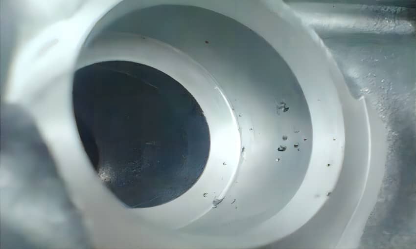
Porosity In Various Casting
Porosity is an inevitable challenge in aluminum casting, but its occurrence varies between low-pressure die casting, high-pressure die casting, gravity die casting, and more.
| Casting Method | Porosity Type | Cause of Porosity | Effect on Casting | Porosity Control |
| Low-Pressure Die Casting (LPDC) | Gas Porosity, Air Entrapment | Slow filling rate and inadequate venting | Minimal porosity, more dense, better structural integrity | Mold venting, degassing techniques, optimized filling |
| High-Pressure Die Casting (HPDC) | Gas Porosity, Air Entrapment, Shrinkage Porosity | High injection speed, rapid solidification, trapped air | Higher porosity, lower density, weak spots | Mold venting, slow injection speed, controlled cooling |
| Gravity Die Casting (GDC) | Gas Porosity, Shrinkage Porosity | Slow pouring, thicker sections, improper venting | Moderate porosity, better control over cooling | Proper mold design, controlled cooling rates, degassing |
Types of Shrinkage Defects
- Shrinkage Porosity
Description: Voids formed due to the contraction of metal as it solidifies.
Causes: Insufficient feed metal during solidification, uneven cooling rates, and inadequate risers or feeders.
Impact: Weakens the mechanical properties of the casting, potentially leading to failure under stress. - Gas Porosity
Description: Voids or bubbles caused by trapped gases within the molten metal.
Causes: Air entrapment during pouring, high levels of dissolved gases in the molten metal, and moisture in the die.
Impact: Affects the surface finish and structural integrity, often leading to cosmetic defects and potential failure points. - Micro Porosity
Description: Tiny, often microscopic, voids distributed throughout the casting.
Causes: Rapid solidification rates, improper alloy composition, and localized solidification shrinkage.
Impact: Reduces the overall strength and elasticity of the casting, making it susceptible to cracking and failure. - Macro Porosity
Description: Larger, visible voids or cavities within the casting.
Causes: Inadequate feeding of molten metal, poor gating design, and insufficient risers.
Impact: Significantly compromises structural integrity and is easily detected through non-destructive testing methods like X-ray or ultrasonic testing. - Surface Porosity
Description: Voids or holes appearing on the surface of the casting.
Causes: Poor die design, inadequate venting, and incorrect alloy temperature.
Impact: This affects the aesthetic quality and may require additional surface treatment to rectify. - Internal Porosity
Description: Voids located within the interior of the casting, often not visible from the surface.
Causes: Inadequate feeding during solidification and improper cooling rates.
Impact: Difficult to detect without destructive testing, but can significantly weaken the casting and cause failure under load. - Interdendritic Porosity
Description: Porosity that forms between the dendritic structures in the metal.
Causes: Rapid cooling and solidification rates, leading to localized shrinkage.
Impact: Reduces mechanical properties and can lead to premature failure under stress. - Blistering
Description: Raised areas or bubbles on the surface of the casting.
Causes: Trapped gases that expand and create blisters as the metal cools.
Impact: Aesthetic defects and potential points of weakness in the casting. - Blind Porosity
Description: Pores that begin on the surface of the casting and extend into the body without passing through.
Causes: Occurs due to trapped gases or shrinkage during solidification.
Impact: Typically does not affect mechanical strength but can lead to corrosion and other defects during surface finishing processes like anodizing. Sealing is required for parts that need to hold pressure. - Through Porosity
Description: Pores that create a leak path from one side of the casting to the other.
Causes: Inadequate feeding during solidification, leading to continuous voids.
Impact: Affects structural integrity and prevents parts from being pressure-tight. These parts are unsuitable for holding gases or fluids but can be sealed from both sides. - Fully Enclosed Porosity
Description: Pores that are fully enclosed within the casting and not visible on the surface.
Causes: Occurs during solidification when internal material contracts and forms voids.
Impact: Not problematic unless exposed to post-machining processes, which can turn them into blind or through pores. Detection typically requires CT scans, X-rays, or part dissection.
Mitigating Shrinkage Porosity
During Design Phase
Simulation analysis during the design phase is essential for new products to predict and eliminate shrinkage defects. Using advanced simulation software, manufacturers can:
- Optimize Casting and Mold Geometry: Design the casting and mold geometry to promote even cooling and feeding.
- Adjust Casting Parameters: Fine-tune parameters like injection speed, pressure, and temperature.
- Design Effective Gating and Cooling Systems: Ensure proper flow and solidification through well-designed gating and cooling channels.
In the Manufacturing Process
For existing products, addressing shrinkage porosity involves modifying die-casting machine parameters and changing the mold design.
Modifying Die Casting Machine Parameters
- Increase Injection Speed and Pressure: Higher injection speed and pressure can reduce air entrapment and prevent shrinkage porosity.
- Optimize Working Temperature: Adjusting the temperature and type of cooling fluid can help manage hotspots and reduce porosity.
- Regular Maintenance: Ensuring the correct functionality of machines through regular maintenance can prevent porosity issues.
Modifying Mold Design
- Redesign Feeding Channels: Modifying the mold runner can slow down feeding channel solidification and increase the compressing effect of the stroke.
- Improve Cooling Systems: Target hotspots by optimizing the cooling system to control solidification rates and reduce thermal gradients.
Advanced Techniques
- Real-Time Monitoring: Implementing real-time monitoring systems with advanced sensors can detect shrinkage porosity as it occurs, allowing for immediate adjustments.
- Vacuum Assisted Casting: Using vacuum techniques can reduce air entrapment and gas porosity.
- Non-Destructive Testing (NDT): X-ray inspection and ultrasonic testing can detect internal shrinkage porosity without damaging the component.
Quality Control Measures
- Controlled Cooling Rates: Design the cooling system to manage solidification rates and minimize thermal gradients.
- Optimize Alloy Composition: Choose aluminium alloys with properties that minimize shrinkage defects.
Case Study: Reducing Casting porosity in Automotive Components
A leading automotive manufacturer faced shrinkage porosity issues in aluminium engine components. By implementing simulation software to optimize mold design and adjusting the working pressure of their die-casting machines, they reduced defects by 30%, leading to improved product quality and significant production cost savings.
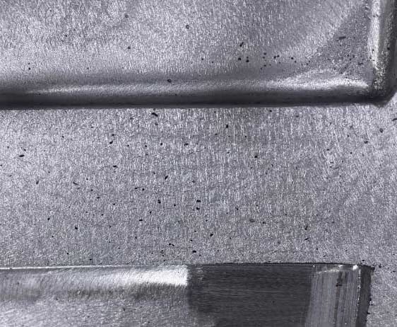
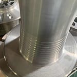
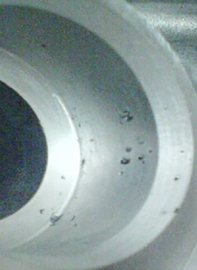
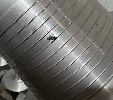
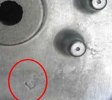
The original design of the cylindrical automotive component featured a lateral feed gate, which resulted in a short feed time. This design flaw caused core misalignment and led to porosity.(see minor-porosity.png) Porosity occurs when air is trapped within the molten material during the casting process, resulting in small holes and voids in the mold as the metal solidifies. Redesigning the feed gate for longitudinal feeding extended the feed time, improved concentricity, and effectively eliminated the porosity.




No comment